
Home
>
Products > Laser Rangefinder Module > 1064nm Laser Target Designator > 40mJ 1064nm Laser Target Designator


40mJ 1064nm Laser Target Designator
The STA-106440M medium laser photometer (hereinafter referred to as the laser photometer) is a precision photoelectric product which transmits the laser to a specific target and calculates the distance information according to the laser flight time. 40mJ 1064nm Laser Target Designator has the characteristics of outstanding performance and simple operation.
Model:JIO-106440M
Send Inquiry
Product Description
40mJ 1064nm Laser Target Designator TECHNICAL SPECIFICATIONS
| Operating mode | Ranging, Illumination | |||
| Operating wavelength | 1.064μm | |||
| Pulse energy | ≥40mJ | |||
| Pulse energy fluctuation | Within one illumination cycle, the fluctuation of a single pulse energy does not exceed 10% of the average energy (counted after emitting light for 2 seconds) | |||
| Beam divergence angle | ≤0.5mrad | |||
| Pulse width | 15ns±5ns | |||
| Laser beam axis stability | ≤0.05mrad (laser beam stability at room temperature of 25℃±5℃) | |||
| Laser beam axis zero-position drift | ≤0.15mrad (laser beam stability at high and low temperatures) | |||
| Alignment error between the optical axis and installation benchmark | Azimuth ≤0.5mrad, Pitch ≤0.25mrad | |||
| Ranging performance | Ranging frequency and maximum continuous measurement time | Ranging frequency | 1Hz/5Hz, single shot | |
| The continuous ranging time of 1Hz is not less than 5 minutes, with 1-minute rest | ||||
| The continuous ranging time of 5Hz is not less than 1 minute, with 1-minute rest | ||||
| Minimum ranging distance | not greater than 300m | |||
| Maximum ranging distance | not less than 5000m | |||
| Ranging accuracy | ±2m | |||
| Target acquisition rate | not less than 98% | |||
| Ranging logic | Initial and final target logic, and final target reporting | |||
| Illumination performance | Illumination distance | ≥3.5km | ||
| Illumination frequency | Fundamental frequency 20Hz | |||
| Coding method | Accurate frequency code | |||
| supporting user-defined accurate frequency | ||||
| Coding accuracy | ±2.5μs | |||
| Irradiation Capability | The duration of each target irradiation is not less than 20 seconds, and the interval between successive irradiations is no more than 30 seconds. The device is capable of continuous irradiation for 10 cycles, and after continuous operation, the interval between successive irradiations must be at least 30 minutes before restarting the continuous irradiation | |||
| The duration of each target irradiation is not less than 47 seconds, and the interval between successive irradiations is no more than 30 seconds. The device is capable of continuous irradiation for 2 cycles, and after continuous operation, the interval between successive irradiations must be at least 30 minutes before restarting the continuous irradiation | ||||
| Service Life | Not less than 1 million times | |||
| Weight | The overall weight of the laser rangefinder/illuminator | ≤500g | ||
| Power Supply Voltage | Voltage | 18V~32V | ||
| Power Consumption | Standby power consumption | ≤4W | ||
| Average power consumption | ≤60W | |||
| Peak power consumption | ≤120W | |||
| Environmental Adaptability | Operating temperature | -40℃~55℃ | ||
| Storage temperature | -55℃~70℃ | |||
CONTROL FUNCTION
The laser rangefinder/illuminator can achieve the following functions through the serial communication interface:
2.1 Respond to laser ranging instructions and can stop ranging at any time according to the stop command;
2.2 During ranging, distance data and status information are output once for each pulse;
2.3 After starting continuous ranging at 1Hz, if no stop command is received, it will automatically stop after 5 minutes;
2.4 After starting continuous ranging at 5Hz, if no stop command is received, it will automatically stop after 1 minute;
2.5 It has a single ranging function;
2.6 It can set the illumination mode and encoding, and can output the selected settings;
2.7 Respond to laser illumination command, illuminate according to the set mode and encoding, and can stop illumination at any time according to the stop command;
2.8 If no stop command is received after starting the illumination, it will automatically stop after one illumination cycle;
2.9 During laser illumination, distance values and status information are output once for each pulse;
2.10 It can report the cumulative number of laser pulses emitted (not lost in case of power failure);
2.11 It can report the cumulative number of laser pulses emitted (not lost in case of power failure);
2.12 The information reported during ranging and laser illumination work includes pulse counting numbers;
2.13 Self-test and output fault codes:
2.13.1 Power-on self-test, including
2.13.1.1 RS422 serial port communication status;
2.13.1.2 High temperature alarm.
2.13.2 Start and cycle self-test, including:
2.13.2.1 RS422 serial port communication status;
2.13.2.2 High temperature alarm;
2.13.2.3 High temperature alarm.
Note: Laser rangefinders/illuminators can only detect charging/discharging and laser emission/non-emission faults when emitting laser beams. Therefore, the power-on self-test does not require detection of the above two types of faults. During startup self-test and periodic self-test, the laser rangefinder/illuminator reports the detection results from the last illumination or ranging. 2.2 Temperature warning output, expected performance during illumination or ranging.
MECHANICAL INTERFACE
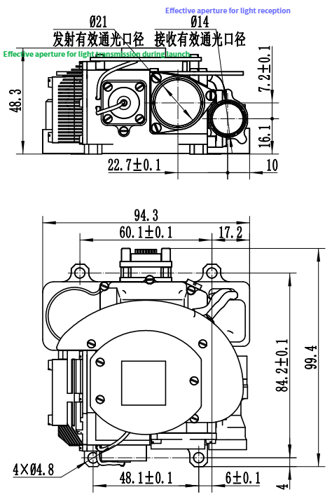
Interface schematic diagram
COMMUNICATION PROTOCOL
4.1 Serial Port Parameters Asynchronous serial communication standard: RS-422;
Baud rate: 115200bps;
Transmission format: 8 data bits, 1 start bit, 1 stop bit, no parity bit;
For each byte of information, the least significant bit (lsb) is transmitted first. If it is a multi-byte message, the low byte is transmitted first.
4.2 Message Format
Baud rate: 115200bps;
Transmission format: 8 data bits, 1 start bit, 1 stop bit, no parity bit;
For each byte of information, the least significant bit (lsb) is transmitted first. If it is a multi-byte message, the low byte is transmitted first.
4.2 Message Format
The communication message format is as follows:
| Header (1 byte) |
| Subsystem ID number |
| Message body |
| Footer (1 byte, i.e., checksum) |
The message body in the above table is described in section 2 "Data Protocol". The header, subsystem ID number, and footer are described in tables 1, 2, and 3, respectively.
Table 1 Description of information header
| Byte name | Data type | Byte length | Value/range of values | Comments |
| Message start code | Unsigned bytes | 1 | 0xCC | Constant |
Table 2 Description of subsystem ID numbers
| Byte names | Data type | Byte length | Value/range of values | comment |
| Subsystem ID number | Unsigned bytes | 1 | 0x08 | Constant |
Table 3 Information Tail (checksum) description
| Name of each byte | Data type | Byte length | Value/range of values | Comments |
| Checksum | Unsigned bytes | 1 | 0-255. | The sum of each byte of the message body part modulo 256. |
The first byte of the 'header' is 0xCC, which is the synchronization code, indicating the beginning of a frame of information; The subsystem ID number is the identification number assigned by the system to the laser rangefinder/illuminator for the system to identify the monomer. The subsystem ID number is 0x08; The message tail is the checksum, which is modulo 256 after summing all the bytes of the message body.
Output Information
Output information refers to the command sent by the system to the laser rangefinder/irradiator. The command information packet is in 6-byte fixed-length format, and the information body is 3-byte. The specific definition is shown in Table 4.
Table 4 Output command information body data format
| Command content | Byte 1 | Byte 2 | Byte 3 | Byte 4 | Byte 5 | Byte 6 |
| Start self-test | 0x01 | N/A | N/A | N/A | N/A | N/A |
| Continuous ranging 5Hz(1min) | 0x02 | N/A | N/A | N/A | N/A | N/A |
| Laser irradiation | 0x03 | Exposure time (27s ~ 60s) | Code 1 to 8 | N/A | N/A | N/A |
| Laser stop | 0x05 | N/A | N/A | N/A | N/A | N/A |
| Pulse times reported | 0x0A | N/A | N/A | N/A | N/A | N/A |
| Product identification reporting | 0x10 | N/A | N/A | N/A | N/A | N/A |
| Laser-coded parameter storage | 0x13 | Code 1 to 8 | Encoding parameter, UINT32 type, the lowest part is first, 43 to 53ms, resolution 0.01ms | |||
| The laser coding storage parameter is confirmed | 0x14 | N/A | N/A | N/A | N/A | N/A |
| Laser coding parameter query | 0x15 | Code 1 to 8 | N/A | N/A | N/A | N/A |
| Single ranging | 0x0B | N/A | N/A | N/A | N/A | N/A |
| Continuous ranging 1Hz(5min) | 0x0C | N/A | N/A | N/A | N/A | N/A |
| Temperature read | 0x06 | N/A | N/A | N/A | N/A | N/A |
Note 1: Laser ranging/irradiator in ranging state, can respond to the illumination command;
Note 2: Laser ranging/illuminator in irradiation, only respond to laser stop command;
Note 3: N/A The default value is 0x00.
Note 2: Laser ranging/illuminator in irradiation, only respond to laser stop command;
Note 3: N/A The default value is 0x00.
Entering Information
Input information refers to the status information received by the system from the laser rangefinder/illuminator. The status message packet is in 9-byte fixed-length format, and the message body is 6-byte, as defined in Table 5.
Table 5 Status message body
| Status content | Byte 1 | Byte 2 | Byte 3 | Bytes 4 to 5 | Pulse count number |
| Power-on self-test response | 0x00 |
Power-on self-test result: 0x00: Normal 0x01: Fault |
When "Power-on self test complete" : Failure code (Note 1) |
N/A | N/A |
| Start the self-test response | 0x01 |
Startup self-test result: 0x00: Normal 0x01: Fault |
When "Boot Self-test complete" : Failure code (Note 1) |
N/A | N/A |
| Continuous ranging 5Hz(1min) | 0x02 |
Fault or not: 0x00: Normal 0x01: Fault |
Laser or not: Failure code (Note 1) |
Laser distance value (Note 2) |
0 to 255 |
| Being irradiated | 0x03 |
Fault or not: 0x00: Normal 0x01: Fault |
Laser or not: Failure code (Note 1) |
Laser distance value (Note 2) |
0 to 255 |
| Laser stop | 0x05 | N/A | N/A | N/A | N/A |
| Return pulse report | 0x0A | N/A | N/A |
Laser pulse count (Note 3) |
N/A |
| Product identification reporting | 0x10 | Identification number 1 (Note 4) | Identification number 2 (Remark 4) | N/A | N/A |
| Laser-coded parameter storage | 0x13 | Code 1 to 8 | Encoding parameter, UINT32 type, the lowest part is first, 43 to 53ms, resolution is 0.01ms, simultaneous transmission | ||
| The laser encoding storage parameter is confirmed | 0x14 | N/A | N/A | N/A | N/A |
| Laser coding parameter query | 0x15 | Code 1 to 8 | Encoding parameter, UINT32 type, the lowest part is first, 43 to 53ms, resolution 0.01ms | ||
| Single ranging | 0x0B |
Fault or not: 0x00: Normal 0x01: Fault |
Laser or not: Failure code (Note 1) |
Laser distance value (Note 3) |
N/A |
| Continuous ranging 1Hz(5min) | 0x0C |
Fault or not: 0x00: Normal 0x01: Fault |
Laser or not: Failure code (Note 1) |
Laser distance value (Note 2) |
0 to 255 |
| Temperature report | 0x06 | N/A | Temperature value (Note 5) | N/A | N/A |
Note 1: Fault codes are judged by bits. 0: Pass 1:fail Bit0 to bit7 represent each SRUs. For details, see Table 6.
Note 2: bit4 and bit5 respectively represent the low and high distance values (distance range: 0 ~ 65535, if the ranging is invalid, set the value to 0);
Note 3: Actual laser pulse number = laser pulse count ×100(Scale=100). (65535*100=6553500 times);
Note 4: The product identification code consists of 2 bytes, byte 2 represents the product ID number of the laser ranging/irradiator (constant 0x05), byte 3 represents the software version number of the laser ranging/irradiator, in which the high four digits represent one digit and the low four digits represent one decimal;
Note 5: Byte 3 is the temperature value, representing the ambient temperature (temperature range -55℃ ~ +125℃);
Note 6: The default value of N/A is 0x00.
Table 6 List of SRU fault codes
| Fault bits (Bits) | SRU name |
| 0 | Spare |
| 1 | Spare |
| 2 | Spare |
| 3 | Spare |
| 4 | Laser not out |
| 5 | Temperature sensor overtemperature |
| 6 | Spare |
| 7 | Spare |
CONTROL THE FLOW
5.1 Message Response
The laser range finder/irradiator is powered on and self-checked. After the completion of the self-test, report the self-test result of power-on and enter the standby state.
After working normally, the system sends a control command to the laser rangefinder/irradiator. After receiving the command, the laser rangefinder/irradiator starts to execute the command and report the status information to the system. The main control process is as follows:
When the system sends the "start self-test" command to the laser rangefinder/illuminator, the laser rangefinder/illuminator actively reports the detailed start self-test result information to the system after the start self-test is completed.
When the system sends the "ranging" command to the laser rangefinder/illuminator, the laser rangefinder/illuminator starts ranging and reports the ranging status and distance value.
When the system sends the "Shine" command to the laser rangefinder/illuminator, the laser rangefinder/illuminator starts to shine and reports the shine status and range value.
When the system sends the "laser stop" command to the laser rangefinder/illuminator, the laser rangefinder/Illuminator stops the laser emission in progress.
When the system sends the "Read Product ID" command to the laser rangefinder/Illuminator, the laser rangefinder/Illuminator replies "Product ID" within the reply timeout.
Passive response timeout: 600ms.
Active reply timeout (only when answering "start self check complete") : 1000ms.
The laser irradiation command has the highest priority, and the laser rangefinder/illuminator should be able to respond to the irradiation command during the ranging process. The laser irradiation process only responds to the stop command, or automatically stops in accordance with the firing time.
5.2 Appendix III Electrical Interface
Electrical connector model: J30J pin 15 core (socket: J30JZLN15ZKWA000, plug: J30JZ/XN15TJCAL01); The corresponding plugs and cables shall be provided by Party B. The interface definition is shown in Table 7:
Table 7 Interface definitions
| Pin number | Label number | Remarks |
| P-1 | VIN+ |
|
| P-2 | VIN+ |
|
| P-3 | NC |
|
| P-4 | VDD | Burn writing |
| P-5 | GND | Burn writing |
| P-6 | ARM_SWCLK | Burn for writing |
| P-7 | ARM_SWDAT | Burn writing |
| P-8 | NC |
|
| P-9 | GND |
|
| P-10 | GND |
|
| P-11 | RS422_TX+ |
|
| P-12 | RS422_TX- |
|
| P-13 | RS422_RX- |
|
| P-14 | RS422_RX+ |
|
| P-15 | GND |
|
Note: Laser ranging/irradiation appliances have power backconnect protection.
Hot Tags: 40mJ 1064nm Laser Target Designator, Manufacturers, Suppliers, Factory, China, Made in China, Customized, High Quality
Related Category
905nm Laser Range Finder Module
1535nm Laser Range Finder Module
1570nm Laser Range Finder Module
1.54um Laser Rangefinder Module
1064nm Laser Target Designator
Anti drone ststem module
Ranging Lidar Module
Send Inquiry
Please feel free to give your inquiry in the form below. We will reply you in 24 hours.


 wiht LRF")
 wiht LRF")